

Insights — Steel Detailing & BIM
From Design to Fabrication: How 3D Steel Detailing Reduces Clashes and Rework
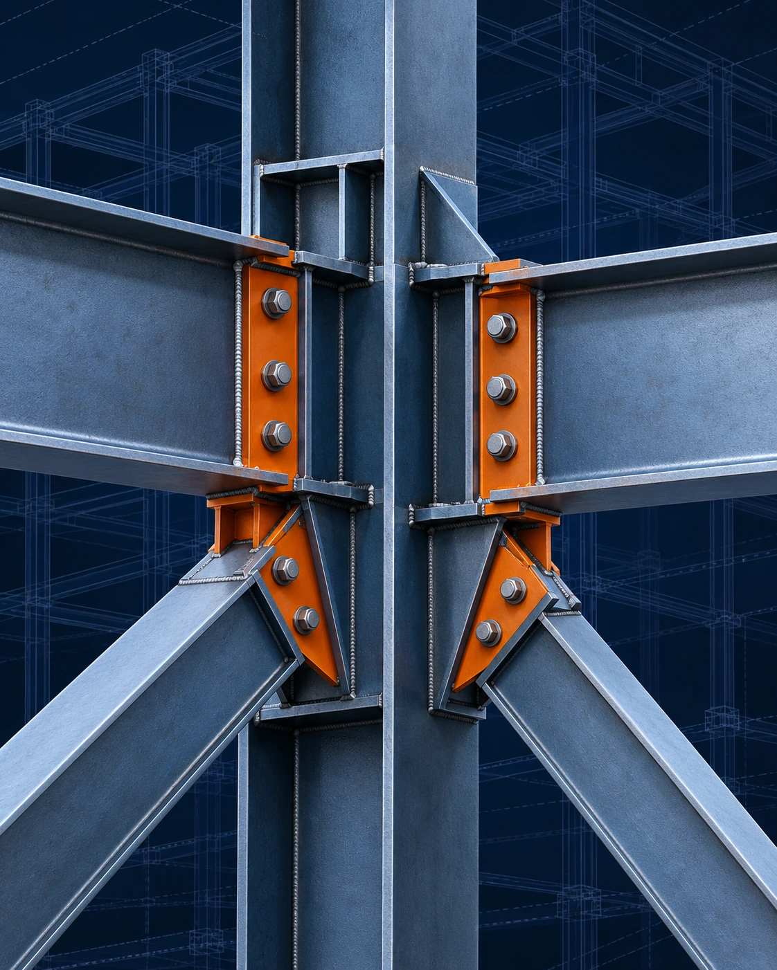
A structural steel member can be fabricated precisely to the specified dimensions and still fail to fit during site erection.
The problem is not always the member itself. It may result from interference between a connection plate and an incoming brace, insufficient clearance for bolt installation, fabrication against an outdated drawing revision, or base plate holes that do not match the surveyed anchor rod positions.
These issues often become apparent only after fabrication or erection has begun. By then, resolving them can require revised shop drawings, workshop modifications, additional transportation, and disruption to the erection schedule.
Effective 3D structural steel detailing helps identify and resolve coordination problems before steel is cut, drilled, or welded.
However, the real value of a 3D model depends on more than software capabilities. It requires reliable design information, a disciplined modeling and checking process, practical connection detailing, and controlled fabrication releases.
01
Design input
Design Drawings Are Not Fabrication Instructions
Structural design drawings establish the engineering intent and technical requirements of a project. They typically define structural arrangements, member sections, grid lines, levels, design loads, connection criteria, general notes, and applicable material specifications.
For the detailing team, the starting point is generally the Issued for Construction (IFC) drawing package, together with the project specifications, general notes, relevant architectural information, and approved technical requirements.
Shop drawings serve a different purpose: translating the approved design into precise instructions for manufacturing, assembly, and installation.
| Design Documentation | Detailing & Fabrication Documentation |
|---|---|
| Structural arrangements and member sections | Individual part and assembly geometry |
| Design loads and connection criteria | Detailed connections, bolts, welds, and plates |
| Grid lines, elevations, and interfaces | Fabrication dimensions and piece marks |
| General notes and material specifications | Shop drawings, material lists, and CNC data |
Before detailed production work begins, the team must identify missing dimensions, conflicting information, unclear connection responsibilities, and discrepancies between disciplines. These issues should be resolved through the project’s formal Request for Information (RFI) and approval procedures.
Key takeaway
A sophisticated 3D model cannot compensate for incomplete or contradictory design information.
02
Model check
Modeling and Checking Before Connection Detailing
One of the most important quality-control steps in steel detailing takes place before the connection detailing phase.
After receiving the IFC drawings and specifications, the detailing team develops the initial 3D structural model. At this stage, the primary focus is accurately representing the approved structural arrangement. The model includes the principal members, section sizes, grid positions, elevations, orientations, and other relevant geometric information.
From this model, the team can generate preliminary erection or general arrangement drawings for checking purposes. These drawings are reviewed against the IFC documentation to verify:
- Correct member section sizes and profiles.
- Grid locations, levels, and structural geometry.
- Member orientation and framing arrangements.
- Completeness of the modeled structural members.
- Consistency with approved drawings and specifications.
This preliminary check is essential because an incorrect section size, misplaced member, or misunderstood framing arrangement can affect numerous connections and fabrication drawings.
Connection detailing should proceed only after the initial model has passed the required geometry and design-conformity checks.
The process does not eliminate subsequent checking. Connection detailing, fabrication drawings, and final deliverables require their own verification before release.
03
Coordination
Resolving Clashes and Constructability Issues
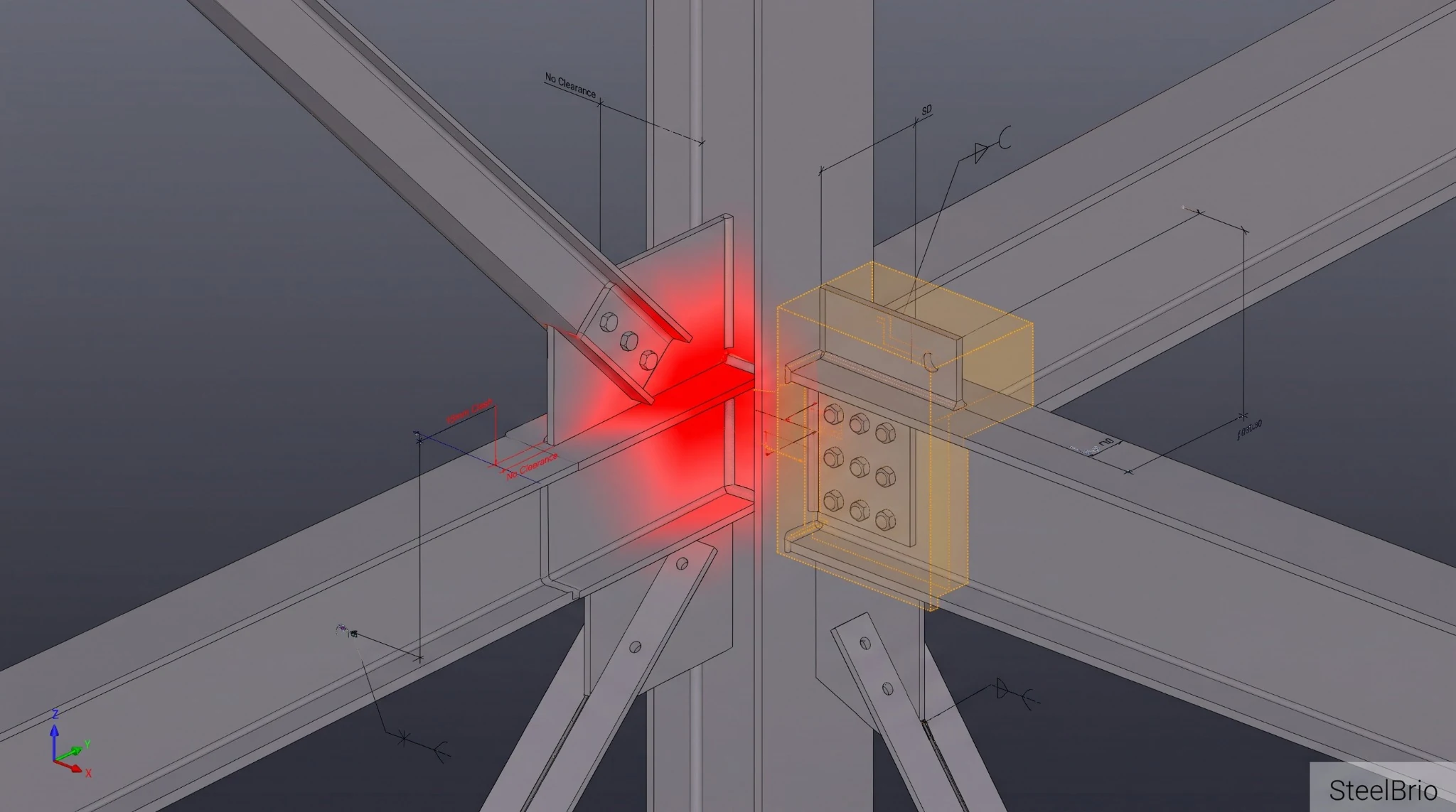
A coordinated 3D model allows detailers and engineers to examine complex structural interfaces that may be difficult to interpret from separate 2D plans and sections. Typical issues include:
- Gusset plate interferenceConnection plates conflicting with adjacent beam flanges, stiffeners, or secondary framing.
- Bracing conflictsMultiple braces intersecting or competing for space at shared structural work points.
- Bolt and tool accessibilityInsufficient clearance for bolt insertion, wrench access, or tightening equipment.
- MEP and façade interfacesStructural elements conflicting with mechanical services, architectural components, or façade support systems.
- Site interfacesBase plates and connection geometry that do not align with verified field conditions.
Software such as Tekla Structures supports geometric clash checking between modeled steel components and reference models. However, automated clash detection is only part of a complete constructability review. A connection may have no detected geometric intersection and still be difficult to assemble, weld, inspect, or install.
A clash-free model is not necessarily a fabrication-ready or erection-ready model.
Practical experience remains essential when evaluating connection access, installation sequences, field tolerances, and workshop capabilities.
04
Connections
Connection Detailing and Constructability
Once the initial structural model has been checked, the detailing team can proceed with connection detailing using the approved design requirements and applicable connection engineering information.
Connection detailing is particularly sensitive because a connection may satisfy structural design requirements while creating unnecessary difficulties during fabrication or erection. The following considerations are essential.
- Engineering responsibilityConfirm whether connection design is provided by the Engineer of Record (EOR) or delegated to a qualified specialty connection design engineer.
- Design informationEnsure that design reactions, moments, connection schedules, and other required engineering parameters are available.
- Bolt accessibilityVerify adequate space for bolt insertion, tightening, and inspection.
- Welding accessConsider welding positions, torch access, weld sequencing, and potential fabrication distortion.
- Fit-up and erection clearancesProvide practical clearances consistent with the approved connection details and applicable standards.
- Coatings and finishesAccount for relevant effects of galvanizing, protective coatings, and fireproofing on connection assembly and accessibility.
Delegated connection design
Where connection engineering is delegated, the responsible qualified engineer must prepare and approve the required calculations and details in accordance with the project specifications and applicable jurisdictional requirements. The detailing team then incorporates the approved connection requirements into the model and fabrication documentation.
05
Shop & CNC
From 3D Models to Shop Drawings and CNC Fabrication
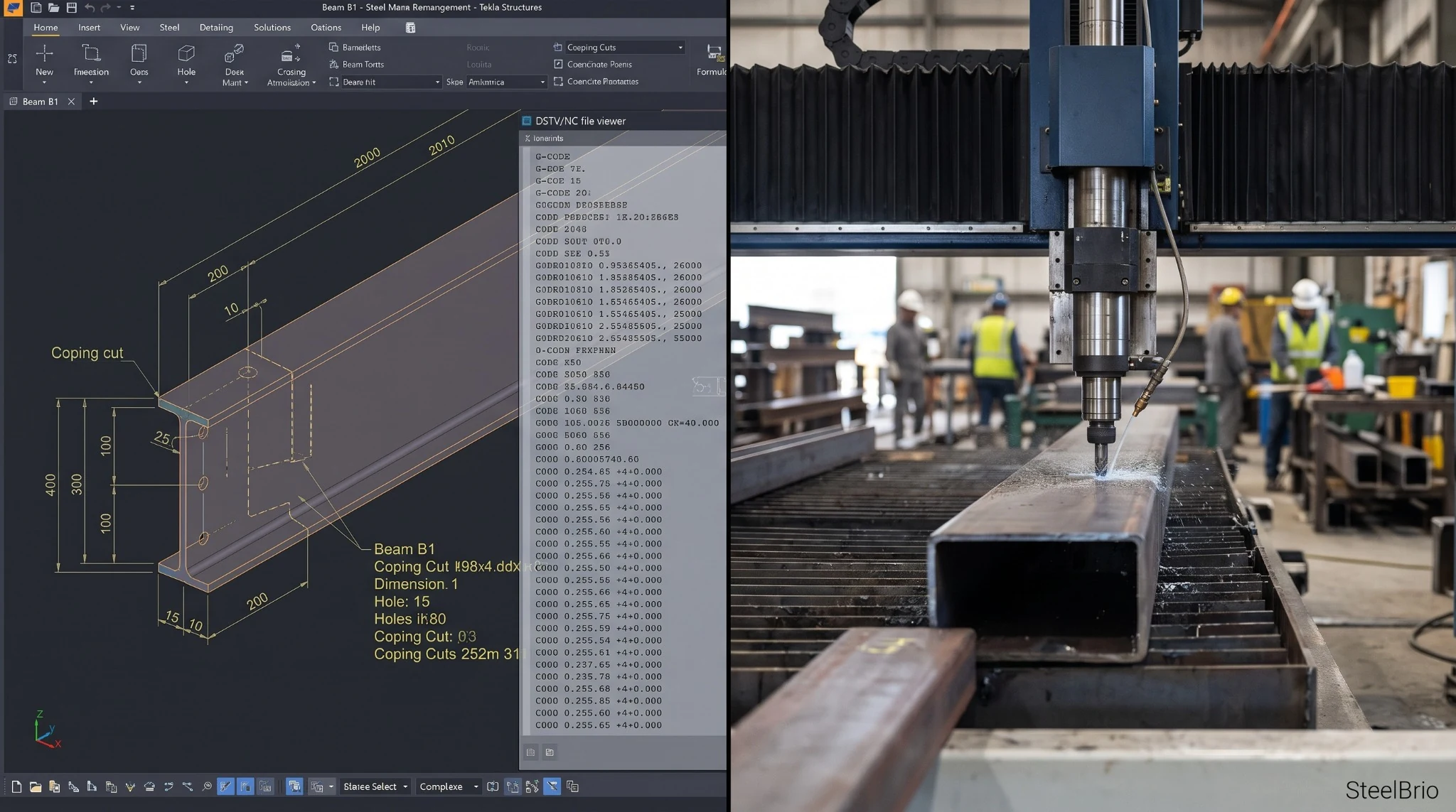
Following connection detailing and the necessary checks, the coordinated model becomes the basis for generating detailed fabrication deliverables. These commonly include:
- Assembly drawingsInstructions showing how individual components are assembled into fabricated steel members.
- Single-part drawingsDimensions, hole patterns, cuts, and other processing details for individual components.
- Final erection drawingsMember locations, piece marks, orientations, and relevant erection information.
- Material take-offs (MTOs)Material quantities, sections, grades, lengths, and other information used for procurement and production planning.
- Machine data filesNC/DSTV, DXF, or other compatible CNC/CAM outputs required by the fabrication facility’s equipment.
- Piece marksIdentifiers connecting individual components and assemblies to drawings, material records, production activities, and erection documentation.
Digital integration between structural models and CNC equipment can substantially reduce manual data-entry errors and improve fabrication efficiency. Nevertheless, model-generated files must still be checked.
The detailing and fabrication teams should verify part orientation, dimensions, hole locations, machine compatibility, piece marks, and applicable revision information before production.
Digital automation improves consistency, but it does not replace technical verification.
06
Release
Revision Control and Formal Fabrication Release
One of the most damaging coordination failures occurs when different project teams work from inconsistent document revisions.
In practice
Consider a connection that has been modified after the material lists were generated while the fabrication workshop continues using an earlier NC file. Even when the revised design is correct, outdated production information can result in scrap, rework, and delivery delays.
A controlled release process should ensure that
- Required design and detailing approvals are documented.
- Fabrication-critical RFIs are resolved and incorporated.
- Shop drawings, material lists, and CNC data correspond to the approved information.
- Superseded drawings and machine files are withdrawn from active production use.
- Fabrication packages are issued through formal, traceable transmittals.
A revision number alone does not authorize fabrication.
For example, Rev 0 does not automatically mean a drawing is approved for manufacturing. The actual approval and release status must be confirmed through the project’s document-control procedure. This distinction is essential when coordinating between detailing offices, engineering teams, fabrication workshops, and project management.
07
Erection
Detailing for Safe and Efficient Erection
Structural steel detailing should consider the requirements of transportation and site installation, not just workshop production. Important coordination areas include:
- Transport constraintsMember lengths, assembly dimensions, vehicle limitations, and delivery arrangements.
- Lifting requirementsAssembly weights, available crane capacities, lifting points, and site access.
- Splice locationsPractical positioning of column, beam, and truss splices to support the planned erection methodology.
- Erection clearancesSuitable fit-up allowances and installation access.
- Field verificationCoordination with site surveys, concrete levels, and anchor rod as-built information.
- Temporary worksCoordination of lifting attachments, temporary stability provisions, and erection-related safety requirements with the responsible specialists.
The erection sequence can also influence how steel members are marked, grouped, transported, and delivered.
Early communication among the detailer, fabricator, and erection contractor helps prevent technically correct fabrication details from becoming difficult or expensive to install.
Workflow
Steel Detailing Workflow: From IFC Drawings to Fabrication
A typical detailing workflow can be summarized in six main stages.
- 01IFC Drawings & SpecificationsReceive and review approved structural drawings, general notes, specifications, and relevant design information.
- 023D ModelingDevelop the initial structural model using the approved framing arrangements, member sections, levels, and geometry.
- 03Preliminary Erection Drawings & Model CheckGenerate preliminary erection drawings and verify the model against the IFC documentation before proceeding with connection detailing.
- 04Connection DetailingDevelop connections based on the approved design requirements, resolve coordination issues, and complete the necessary technical checks.
- 05Shop & Final Erection DrawingsPrepare assembly drawings, single-part drawings, final erection drawings, and associated material information.
- 06Final Check & Fabrication PackageComplete final verification and issue the approved fabrication package, including applicable CNC/NC/DSTV files, under controlled release procedures.
The exact checking, approval, and submission stages may vary according to project requirements and contractual responsibilities.
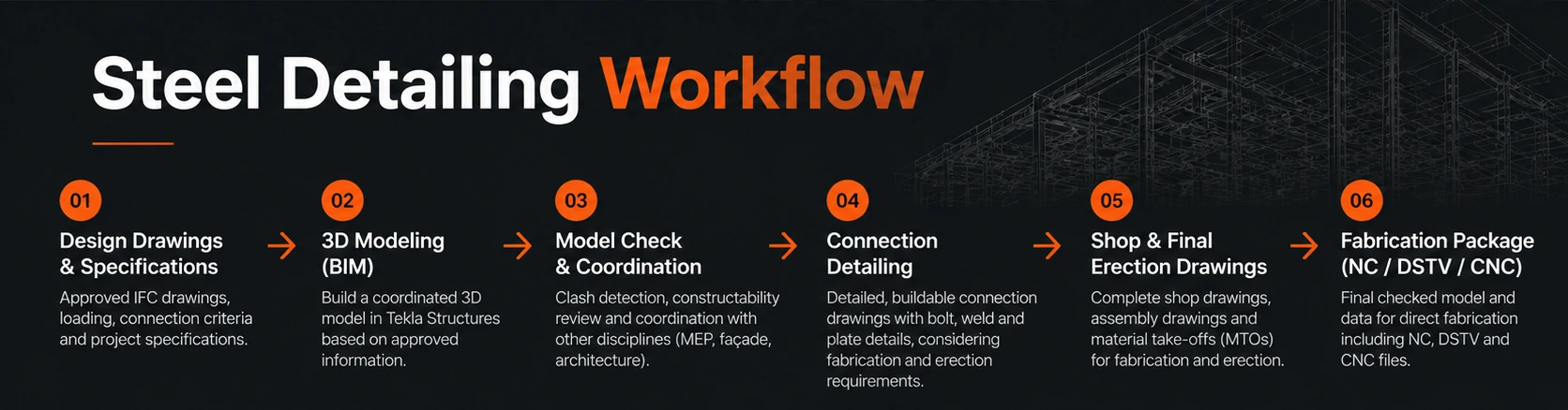
Note on the illustration: its stage 03 is labelled “Model Check & Coordination” and its final stage describes data for direct fabrication. The six stages listed above are the reference sequence: stage 03 is the preliminary model check against the IFC documentation, clash and constructability review continues through connection detailing, and fabrication data is used only after controlled release.
Checklist
The Pre-Fabrication Coordination Checklist
Before a structural steel package is released for manufacturing, the responsible project team should complete a documented technical review.
| Review Area | Verification Objective |
|---|---|
| Design Status | Approved drawings, specifications, and engineering responsibilities confirmed |
| Initial Model | Member sizes, grid positions, elevations, and framing geometry checked |
| Connections | Required calculations, connection criteria, and approvals documented |
| Geometry & BIM | Relevant clashes and constructability issues resolved |
| Site Interfaces | Critical survey and anchor rod information incorporated |
| Materials | Grades, finishes, quantities, and specifications verified |
| Shop & CNC Data | Drawings, piece marks, and machine files cross-checked |
| Revision Control | Superseded information withdrawn and approved release documented |
| Erection Logistics | Transport, lifting, access, and erection sequence coordinated |
This review helps establish a consistent technical basis for fabrication and reduces the likelihood of avoidable workshop and site modifications.
Our Approach
How SteelBrio Supports the Process
SteelBrio connects structural steel detailing, technical coordination, material sourcing, and fabrication execution through qualified specialist partners. We coordinate engineering and detailing requirements, connection design interfaces, fabrication deliverables, and subcontracting activities in accordance with approved drawings, project specifications, and applicable standards.
Our approach focuses on identifying coordination issues early, maintaining controlled technical information, and supporting reliable fabrication and erection outcomes.
Responsibilities
Engineering design and fabrication responsibilities remain with the appropriately qualified parties.
Let’s Connect
Planning a Structural Steel Project?
Send us your project drawings, specifications, or technical requirements to discuss steel detailing, engineering coordination, sourcing, and fabrication support.
Technical References & Further Reading
- American Institute of Steel Construction (AISC). ANSI/AISC 303, Code of Standard Practice for Steel Buildings and Bridges. aisc.org
- Research Council on Structural Connections (RCSC). Specification for Structural Joints Using High-Strength Bolts. boltcouncil.org
- Trimble. Tekla Structures user assistance, official documentation covering modeling, clash checking, drawings and fabrication outputs. support.tekla.com
These references provide background guidance. The applicable editions, approvals and contractual responsibilities must be confirmed for each project and jurisdiction.